Understand a drawing converted in part
Who can do this
Anyone who can open the project. Replacing the drawing needs permission to add files to it. Every plan.
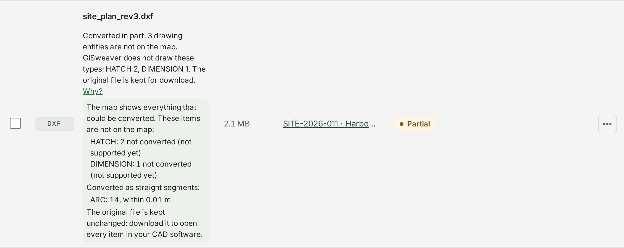
A DXF drawing with hatches, dimensions or other items GISweaver does not draw reads Partial: the rest is drawn as usual, and the file says what was left out.
- Find the file in the project's Files list or on Uploads. It reads Partial, and the line under its name reads Some items not shown with a count and the kinds.
-
Select Why? on that line. It lists each kind, how many items were not converted and why, and how many curves were drawn as straight segments, and within what distance.
-
Decide whether what was left out matters on the map. If it does not, there is nothing to do.
- If it does, fix the drawing in your CAD software (a hatch to its boundary polyline, a dimension to lines and text), add the corrected file to the project, then delete this one.
What happens next
The drawing stays on the map with everything that could be converted. The original file is kept unchanged: download it from the file's ⋯ menu to open every item in your CAD software.
If something goes wrong
- The reason reads blocks nested too many levels deep or the block is not in the drawing. Blocks nested more than eight deep, and a reference to a block the drawing does not contain, are left out. Explode the block in your CAD software, add the corrected file, then delete this one.
- The file reads Ready with 1 entity was off the site and was left out. (or more): an item lay outside the area the project covers, often a stray line at 0,0. If it was meant to be there, check the drawing's coordinate system, add the corrected file, then delete this one.
Details
What is drawn
A DXF drawing is drawn on the map from its lines, polylines, points, text, circles, arcs, ellipses, splines and block references.
How curves are drawn
An arc in a polyline, a circle, an arc, an ellipse and a spline are drawn as short straight segments, none more than 0.01 of the drawing's unit from the true curve: 1 cm in a project in metres.
Blocks and layers
A block is drawn where it is inserted, at its scale and rotation, with its attributes as labels; an item of the block on layer 0 takes the insert's layer, as CAD shows it. Every layer is kept, and titled on the map by its own name.
Words used across these pages are in the glossary.
Next: Delete a file